Minimig Board v1.0 schematic
Jump to navigation
Jump to search


Board schematic for Minimig board v1.0

Voltage level: (3.3V/(560ohm + 560ohm + 32ohm))*32 ohm*1000 = 91,7mV
Back EMF issues?
Head phones

Notice the resistor of 560 ohm. May cause inlinear output.
- in 15kHz mode:
- /VSYNC = high (scart RGB enable)
- /HSYNC = composite sync

IC5 - FPGA Xilinx XC3S400-4PQ208C

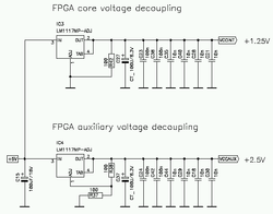
IC3/IC4 - FPGA core power +1,25V +2,5V using LM1117MP-ADJ

FPGA decoupling


J7 - Jtag


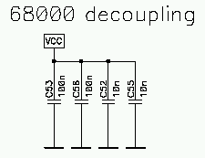
MC68000 Decoupling

PATCH needed to get rev 1 board working:
- Disconnect net SPI_DOUT from pin 81 of FPGA.
- Connect net SPI_DOUT to pin 19 of FPGA (net USER3).
- REASON:
- Pin 81 is an output during FPGA config that blocks SPI to MMC during startup.


IC6/IC7 - Asynchronous static ram 512 x 16 bit (2 chips)


J11 - SD Card slot
