Minimig Board v1.1 documentation
Jump to navigation
Jump to search
- The wire patch needed for rev1.0 to work is now incorporated into the layout. So, rev1.1 doesn't need a single wire patch.
Pin FPGA Name v1.0 Assignment v1.1 Assignment Comment 19 IO_7 User3 SPI_DOUT 79 IO_4/GCLK0 RAM_A15 RAM_A15 81 IO_4/DOUT SPI_DOUT NC
- SD/MMC: R49 has been decreased from 1000 to 100 Ohm for better MMC-Card compatibility.
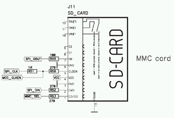 J11 - SD Card slot

- The PS/2 connectors are now properly connected to the frame ground.
- J5 - pin7,pin8,pin9 wired to "FRAME1"
- J8 - pin7,pin8,pin9 wired to "FRAME1"
- The bottom silk screen has been cleaned up and added to the gerber file set. Minimig rev1.1 is 100% core and firmware compatible with the rev1.0 PCB. Although it has not been built by me (and therefore has not been verified by me), it passes all design rule checks so I trust it will work. The rev1.1 PCB (like rev1.0) has been designed using rather "relaxed" design rules so any PCB manufacturer should be able to produce it.